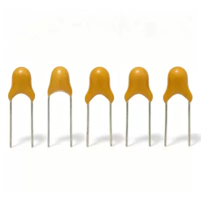
Monolithic Ceramic Capacitor
Product Description
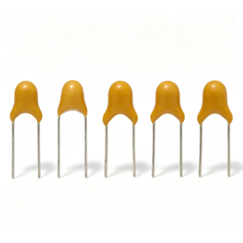
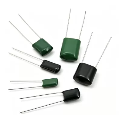
The CT4 radial leaded multilayer ceramic capacitor (MLCC) features a compact size, high capacitance-to-volume ratio and reliable electrical performance. It is suitable for coupling, bypassing, filtering, energy storage and general-purpose electronic circuits.
Available dielectric materials include C0G/NPO, X7R, Y5V and Z5U, with different capacitance ranges and temperature characteristics for various circuit requirements.
Product Specification
| Item | Specification |
|---|
| Product Type | Class II Radial Leaded Ceramic Capacitor |
| Part Number | CT4-0805Y104M500 |
| Dielectric Material | Y5V |
| Nominal Capacitance | 100,000 pF / 100 nF / 0.1 μF |
| Capacitance Tolerance | ±20% |
| Rated Voltage | 50 VDC |
| Body Size | 4.2 × 3.8 mm maximum |
| Lead Spacing | 5.0 ± 0.12 mm |
| Packaging | Bulk packaging unless otherwise specified |
Dielectric Options
| Dielectric | Type | Capacitance Range | Temperature Characteristics |
|---|
| C0G/NPO | Class I | 1 pF–4.7 nF | 0 ±30 ppm/°C, -55°C to +125°C |
| X7R | Class II | 100 pF–2.2 μF | ±15%, -55°C to +125°C |
| Y5V | Class II | 1 nF–4.7 μF | +30%/-80%, -30°C to +85°C |
| Z5U | Class II | 1 nF–4.7 μF | +30%/-80%, -30°C to +85°C |
Typical Applications
C0G/NPO
Suitable for circuits requiring highly stable electrical performance, including temperature-compensation and high-frequency oscillation circuits.
X7R
Suitable for DC blocking, coupling, bypassing, filtering and frequency-discrimination circuits where moderate capacitance stability is acceptable.
Y5V and Z5U
Suitable for circuits requiring higher capacitance in a compact size, including energy-storage, filtering and memory-related circuits.
Part Number Identification
CT4-0805Y104M500
| Code | Meaning |
|---|
| CT4 | Class II radial leaded ceramic capacitor |
| 0805 | Maximum body dimensions: 4.2 × 3.8 mm |
| Y | Y5V dielectric |
| 104 | 100,000 pF / 0.1 μF |
| M | ±20% capacitance tolerance |
| 500 | 50 V rated voltage |
| Blank Packaging Code | Bulk packaging |
Product Type Codes
| Code | Product Type |
|---|
| CT4 | Class II dielectric radial leaded capacitor |
| CC4 | Class I dielectric radial leaded capacitor |
Body Size Codes
| Size Code | Maximum Body Size |
|---|
| 0805 | 4.2 × 3.8 mm |
| 1206 | 5.0 × 4.5 mm |
| 1210 | 7.6 × 5.5 mm |
| 1812 | 8.0 × 8.0 mm |
| 2225 | 10.5 × 9.5 mm |
| 3035 | 12.5 × 10.5 mm |
Dielectric Codes
| Code | Dielectric |
|---|
| N | C0G/NPO |
| B | X7R |
| Y | Y5V |
| E | Z5U |
Capacitance Tolerance Codes
| Code | Tolerance |
|---|
| B | ±0.10 pF |
| C | ±0.25 pF |
| D | ±0.5 pF |
| F | ±1% |
| G | ±2% |
| J | ±5% |
| K | ±10% |
| M | ±20% |
| S | +50%/-20% |
| Z | +80%/-20% |
| P | +100%/-0% |
B, C and D tolerances apply to capacitance values below 10 pF.
- C0G/NPO: B, C, D, F, G, J, K and M
- X7R: K, M, S and Z
- Y5V/Z5U: M, S, Z and P
Rated Voltage Codes
| Code | Rated Voltage |
|---|
| 250 | 25 V |
| 500 | 50 V |
| 630 | 63 V |
| 101 | 100 V |
Electrical Performance
| Item | C0G/NPO | X7R | Y5V/Z5U |
|---|
| Capacitance | Within specified tolerance | Within specified tolerance | Within specified tolerance |
| Dissipation Factor | ≤0.15% when CR ≥50 | ≤3.5% | ≤3.5% below 220 nF; ≤5% from 220–470 nF; ≤7.5% from 470–1,000 nF |
| Insulation Resistance | C≤10 nF: >10,000 MΩ; C>10 nF: RC>100 s | C≤25 nF: >4,000 MΩ; C>25 nF: RC>100 s | C≤25 nF: >4,000 MΩ; C>25 nF: RC>100 s |
| Withstanding Voltage | 1.5 × rated voltage + 500 V for 5 seconds; current ≤50 mA | Same | Same |
Test Conditions
| Item | Specification |
|---|
| C0G/NPO Test Frequency | 1 MHz or 100 kHz; 1 kHz when capacitance exceeds 1,000 pF |
| X7R Test Frequency | 1 kHz |
| Y5V/Z5U Test Frequency | 1 kHz |
| C0G/NPO and X7R Test Voltage | 1 ±0.2 VDC |
| Y5V/Z5U Test Voltage | 0.3 ±0.2 VDC |
| Insulation Resistance Test Voltage | Equal to rated voltage |
| Maximum Charging Current | 50 mA |
| Standard Test Temperature | 15°C–35°C |
| Standard Relative Humidity | 45%–75% |
| Standard Atmospheric Pressure | 86–106 kPa |
| Arbitration Temperature | 25 ±1°C |
| Arbitration Relative Humidity | 48%–52% |
Operating Temperature
| Dielectric | Operating Temperature |
|---|
| C0G/NPO | -55°C to +125°C |
| X7R | -55°C to +125°C |
| Y5V | -25°C to +85°C |
| Z5U | +10°C to +85°C |
Reliability Test Requirements
- No visible damage or unclear markings after testing.
- Capacitance must remain within the specified tolerance.
- Insulation resistance must remain within the specified range.
- Terminal-to-terminal and terminal-to-body withstand-voltage tests must produce no breakdown or flashover.
- Solder heat resistance: 260 ±5°C for 10 seconds.
- Solderability test: 260 ±5°C for 2 seconds.
- Endurance test: 1.5 times rated voltage at the upper-category temperature for 100 hours.
- Recovery time after relevant tests: 24 ±2 hours.
Packaging Options
| Code | Packaging Style |
|---|
| A | Ammo packaging |
| T | Reel packaging |
| Blank | Bulk packaging |
Available packaging includes bulk, ammo and reel packaging.
Storage Conditions
- Storage temperature: 5°C–35°C
- Relative humidity: 45%–75%
- Recommended storage period: 1 year