
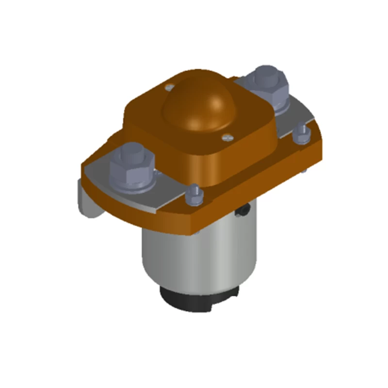

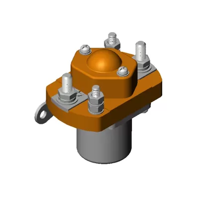

The ZLJ-400A/27 DC contactor is designed for switching and controlling high-current DC power circuits. It is widely used in battery-powered vehicles, electric forklifts, electric winches, electric vehicles, excavators, automotive air-conditioning systems and communication power supplies.
Key Features
400 A contact-switching capacity.
Single normally open contact configuration.
16.5 W coil power consumption.
Silver-alloy contacts for reliable high-current switching.
Suitable for continuous-duty operation.
Compliant with RoHS requirements.
Suitable for telecommunications equipment, construction machinery, vehicles, trains, ships and UPS systems.
Technical Specifications
Item
Specification
Model
ZLJ-400A/27
Product Type
DC Contactor
Contact Configuration
1H, SPST-NO
Contact Material
Silver alloy
Rated Contact Load
400 A × 48 VDC, resistive load, DC-1
Rated Coil Voltage
27 VDC
Coil Power Consumption
16.5 W
Coil Operating Voltage
85%–110% of rated coil voltage
Pick-Up Voltage
45%–70% of rated coil voltage
Drop-Out Voltage
5%–40% of rated coil voltage
Starting Current at 27 VDC and 20°C
≤5 A
Holding Current at 27 VDC and 20°C
≤0.6 A
Contact Voltage Drop
≤80 mV at 400 A
Insulation Resistance
≥100 MΩ at 500 VDC
Dielectric Strength
1,000 VAC, 50/60 Hz for 1 minute
Leakage Current During Dielectric Test
<1 mA
Pick-Up Time
≤30 ms
Release Time
≤30 ms
Operating Temperature
-25°C to +60°C
Storage Temperature
-40°C to +65°C
Relative Humidity
20%–90% RH
Vibration Resistance
10–200 Hz, acceleration ≤3.5 g
Shock Resistance
60–100 impacts/min, acceleration ≤4 g
Mechanical Life
100,000 operations without load
Electrical Life
6,000 operations at rated load
Pollution Degree
III
Duty Cycle
Continuous duty
Model Number Identification
ZLJ-400A/27
ZLJ: Design code for a normally open DC contactor.
400A: Rated current of 400 A under a DC-1 resistive load.
27: Rated coil voltage of 27 VDC.
Example: ZLJ-400A/27 indicates a normally open DC contactor rated for a 400 A × 48 VDC resistive load, with a 27 VDC coil.
Typical Applications
Battery-powered vehicles
Electric forklifts and winches
Electric and hybrid vehicles
Excavators and construction machinery
Automotive air-conditioning systems
Telecommunication power supplies
Uninterruptible power supplies
Railway and marine electrical systems
Installation and Safety Precautions
Tighten the main-circuit terminal screws and nuts to 10–13 N·m. Tighten the control-circuit terminal screws and nuts to 1–1.5 N·m.
The coil-driving circuit must provide power equal to or greater than the required coil power. Insufficient power may reduce the contactor’s breaking performance.
Do not continuously apply a coil voltage exceeding the maximum allowable value. Excessive voltage may cause abnormal coil heating and shorten insulation life.
This contactor is not waterproof. Do not use it where water, solvents or oil may contact the housing or terminals. Exposure may cause housing deterioration, terminal corrosion, contamination or abnormal heating.
Drawing Note
The outline dimensions, mounting dimensions, model-identification graphics and circuit diagram use local computer paths and were not included in the supplied content. Please upload the original images separately if they need to be extracted.